Optical fiber measurement with OTDR can be divided into three steps: parameter setting, data acquisition and curve analysis. Manual setting of measurement parameters includes:
(1) Wavelength selection (λ):
Because different wavelengths correspond to different light characteristics (including attenuation, micro bending, etc.), the test wavelength generally follows the principle corresponding to the system transmission communication wavelength, that is, when the system opens 1550 wavelength, the test wavelength is 1550nm.
(2) Pulse Width:
The longer the pulse width, the larger the dynamic measurement range and the longer the measurement distance, but the greater the blind zone in the OTDR curve waveform; the short pulse injection level is low, but the blind zone can be reduced. The pulse width period is usually expressed in ns.
(3) Measuring range (Range):
The OTDR measurement range refers to the maximum distance for the OTDR to obtain data samples. The selection of this parameter determines the size of the sampling resolution. The best measurement range is between 1.5 to 2 times the length of the fiber to be tested.
(4) Average time:
Since the backscattered light signal is extremely weak, statistical averaging is generally used to improve the signal-to-noise ratio. The longer the averaging time, the higher the signal-to-noise ratio. For example, the gain of 3min will be higher than the gain of 1min
0.8dB dynamic. However, the acquisition time of more than 10 minutes does not significantly improve the signal-to-noise ratio. Generally, the average time does not exceed 3 minutes.
(5) Optical fiber parameters:
The setting of optical fiber parameters includes the setting of refractive index n and backscattering coefficient n and backscattering coefficient η. The refractive index parameter is related to the distance measurement, and the backscattering coefficient affects the measurement results of reflection and return loss. These two parameters are usually given by the fiber manufacturer.
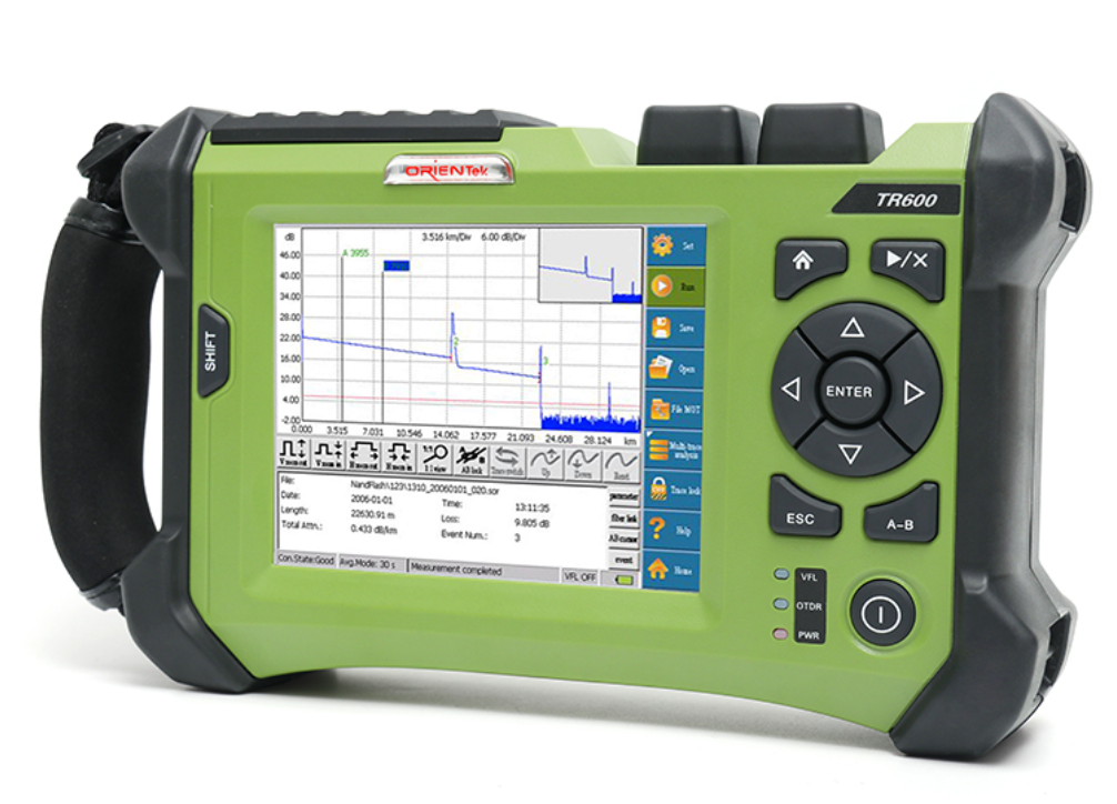
After the parameters are set, the OTDR can send light pulses and receive the light scattered and reflected by the optical fiber link, sample the output of the photodetector to obtain the OTDR curve, and analyze the curve to understand the fiber qual.
(6) Simple judgment of fiber quality:
Under normal circumstances, the slope of the main body of the light curve (single disk or several optical cables) tested by OTDR is basically the same. If the slope of a certain section is large, it indicates that the attenuation of this section is large; if the main body of the curve is of irregular shape, the slope fluctuates greatly. Bending or arcing indicates that the quality of the optical fiber is seriously degraded and does not meet the communication requirements.
(7) Wavelength selection and unidirectional and bidirectional test
The 1550 wavelength test distance is farther, 1550nm is more sensitive to bending than 1310nm fiber, 1550nm is less attenuation per unit length than 1310nm, and the fusion or connector loss measured at 1310nm is higher than 1550nm. In actual fiber optic cable maintenance work, the two wavelengths are generally tested and compared. Both the positive gain phenomenon and the line exceeding the distance must be subjected to two-way test analysis and calculation to obtain a good test conclusion.
(8) Connector cleaning:
Before connecting the optical fiber connector to the OTDR, it must be carefully cleaned, including the output connector of the OTDR and the tested live connector, otherwise the insertion loss is too large, the measurement is unreliable, the curve is noisy or even the measurement cannot be performed, and it may damage the OTDR. Avoid using other cleaning agents or refractive index matching fluids other than alcohol, because they can dissolve the adhesive in the optical fiber connector.
(9) Correction of refractive index and scattering coefficient: For fiber length measurement, every 0.01 deviation of the refractive index will cause an error of as much as 7m/km. For longer light sections, the refractive index provided by the fiber optic cable manufacturer should be used valiantly.
(10) Use of additional optical fiber:
The additional optical fiber is a 300-2000m long optical fiber used to connect the OTDR and the optical fiber to be tested. Its main functions are: front-end blind zone processing and terminal connector insertion measurement.
Generally speaking, the blind zone caused by the connector between the OTDR and the fiber under test is the largest. In the actual fiber measurement, a transition fiber is added between the OTDR and the fiber to be tested, so that the front-end blind zone falls in the transition fiber, and the beginning of the fiber to be tested falls in the linear stable region of the OTDR curve. The insertion loss of the connector at the beginning of the fiber optic system can be measured by adding a transition fiber to the OTDR. To measure the insertion loss of the connectors at the head and tail ends, add a transition fiber at each end.